
Quantum Efficiency Tester
PL/EL Integrated System
PV-Reflectumeter
3D Confocal Microscope
In-Line Four Point Probe Tester
Four Point Probe Tester
In-Line Thin Film Thickness Tester
Raman Spectrometer
FTIR Spectrometer
Spectrophotometer
Automatic Spectroscopic Ellipsometer
Contact Resistance Tester
Ultra depth of field 3D microscope
Auto Visual Tester
VMM PV Vision Measuring Machine
Solar Cell Horizontal Tensile Tester
Steady State Solar Simulator for Solar Cell
Solar Cell UV Aging Test Chamber
Solar Cell Comprehensive Tensile Tester
Visual Inspection Tester
Wet Leakage Current Tester
PV Module EL Tester
PV Module UV Preconditioning Chamber
Steady State Solar Simulator for PV Module
Current Continuous Monitor
Potential Induced Degradation Test
Bypass Diode Tester
LeTID Test System
Reverse Current Overload Tester
Impulse Voltage Tester
Hipot Insulation Tester
Ground Continuity Tester
Hipot Insulation Ground Tester
Damp Heat Test Chamber
Humidity Freeze Test
Thermal Cycle Test Chamber
Dynamic Mechanical Load Tester
Static Mechanical Load Tester
Hail Impact Tester
Robustness of Termination Tester
Module Breakage Tester
Cut Susceptibility Tester
Peel Shear Strength Tester
Universal Testing Machine (Single-arm)
Universal Testing Machine (Double-arm)
Glass Transmittance Tester
Acetic Acid Test Chamber
EVA Degree of Crosslinking Test System
Junction Box Comprehensive Tester
Drop ball tester
Semi-automatic scanning four-probe tester
Stylus Profilometer
Maximum Power Point Tracker
Perovskite Glass Transmittance Tester
Perovskite P1 Laser Scribing Multifunctional Testing Machine
Perovskite Online PL Tester
Perovskite Online Sheet Resistance Tester
Online Perovskite Film Thickness Tester
Perovskite Process Inspection Workstation
Portable EL Tester
Portable Thermal Imaging Tester
Solar Module Multi-Channel Testing System
PV Inverter Power Quality Tester
Drone EL Tester
IV Tester
IVEL Cell Sorting Machine
Principles of EL Testing for Solar Panels
Date : 17 October 2025Views : 1600
The principle of EL testing involves applying a forward current to solar panels, causing them to actively emit light like light-emitting diodes (LEDs). An infrared camera captures the emitted near-infrared light, enabling diagnosis of internal defects and performance inhomogeneities based on the distribution of light intensity.
I. Step-by-Step Analysis of EL Testing Mechanism
EL Testing Mechanism
1. Theoretical Basis: Reversibility of the Photoelectric Effect in Semiconductor PN Junctions
Photovoltaic Effect (Forward): The core of a solar cell is a PN junction. Under illumination, photons excite electron-hole pairs, which separate under the built-in electric field to generate current and voltage—converting light energy into electrical energy.
Electroluminescence Effect (Reverse): This process is reversible. When a forward bias is applied to the solar cell's PN junction (i.e., connecting the positive terminal to the cell's positive electrode and the negative terminal to the cell's negative electrode), it injects non-equilibrium charge carriers (electrons and holes). As these carriers recombine near the PN junction, they release energy in the form of photons—the process of converting electrical energy into light energy. This constitutes the physical foundation of EL testing.
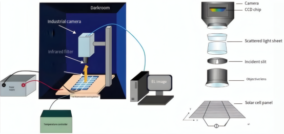
2. Key Components and Workflow
DC Power Supply: Provides an adjustable forward bias current to the entire module. The current magnitude typically ranges between 5%–20% of the module's short-circuit current (Isc).
Darkroom Environment: Testing must be conducted in complete darkness, as the light emitted by solar cells is extremely faint (primarily near-infrared) and any ambient light will interfere with imaging.
Infrared Camera: The system's “eyes.” The light emitted by standard silicon-based solar cells during electroluminescence primarily occurs around 1150nm (near-infrared spectrum), invisible to the human eye. Therefore, specialized cameras sensitive to near-infrared light are required (typically silicon-based CCD or InGaAs cameras, with the latter being more sensitive to longer wavelengths).
Computer and Control Software: Controls power output, camera exposure time, and acquires, processes, and displays EL images.
II. EL Testing Workflow:
Component Placement: Place the solar panel under test into the dark box and correctly connect its positive and negative terminals to the DC power supply.
Current Application: Turn off the light source. The software controls the power supply to inject a specified forward DC current into the module.
Image Acquisition: The infrared camera captures images of the illuminated module. Exposure time typically ranges from several hundred milliseconds to several seconds, depending on the current magnitude and camera sensitivity.
Image Analysis: The computer acquires grayscale images (EL images). Technicians assess the module's intrinsic quality based on the image's brightness contrast.
III. How to Interpret EL Images?
In EL images, brightness directly reflects the intensity of carrier recombination luminescence in that area, thereby indicating the current generation capability and quality of the solar cell in that region.
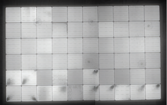
Common Defect Images in Module EL Testing
Bright, uniform areas: Indicate good performance in that region. Current flows smoothly, with strong carrier recombination luminescence.
Dim or black areas: Indicate defects in that region, resulting in weak or absent carrier recombination luminescence. Causes include:
Cracks: Hidden cracks, broken grids, etc. Cracks block current pathways, preventing current flow and luminescence behind the crack, appearing as distinct black lines in the image.
Breakage: Fragmentation of the cell, operating on the same principle as cracks.
Printing/Burning Defects: Improper grid line printing or sintering, resulting in excessively high series resistance or localized short circuits.
Material Defects: Such as dislocations or impurities. These defects act as carrier recombination centers, causing carriers to dissipate energy through “non-radiative recombination” (heat generation) at the defect site before luminescent recombination occurs. Consequently, this area exhibits reduced light emission.
Low-Efficiency Cells or Mixed Batches: Cells with differing efficiencies emit varying intensities under the same current; lower-efficiency cells appear dimmer.
Black Core: Darkening in the central region of the cell, typically associated with silicon ingot resistivity variations or texturing issues.
Black Edge: Darkening along the cell edges, usually caused by insufficient edge etching or contamination reducing parallel resistance, resulting in edge leakage.
Related Products


