
Quantum Efficiency Tester
PL/EL Integrated System
PV-Reflectumeter
3D Confocal Microscope
In-Line Four Point Probe Tester
Four Point Probe Tester
In-Line Thin Film Thickness Tester
Raman Spectrometer
FTIR Spectrometer
Spectrophotometer
Automatic Spectroscopic Ellipsometer
Contact Resistance Tester
Ultra depth of field 3D microscope
Auto Visual Tester
VMM PV Vision Measuring Machine
Solar Cell Horizontal Tensile Tester
Steady State Solar Simulator for Solar Cell
Solar Cell UV Aging Test Chamber
Solar Cell Comprehensive Tensile Tester
Visual Inspection Tester
Wet Leakage Current Tester
PV Module EL Tester
PV Module UV Preconditioning Chamber
Steady State Solar Simulator for PV Module
Current Continuous Monitor
Potential Induced Degradation Test
Bypass Diode Tester
LeTID Test System
Reverse Current Overload Tester
Impulse Voltage Tester
Hipot Insulation Tester
Ground Continuity Tester
Hipot Insulation Ground Tester
Damp Heat Test Chamber
Humidity Freeze Test
Thermal Cycle Test Chamber
Dynamic Mechanical Load Tester
Static Mechanical Load Tester
Hail Impact Tester
Robustness of Termination Tester
Module Breakage Tester
Cut Susceptibility Tester
Peel Shear Strength Tester
Universal Testing Machine (Single-arm)
Universal Testing Machine (Double-arm)
Glass Transmittance Tester
Acetic Acid Test Chamber
EVA Degree of Crosslinking Test System
Junction Box Comprehensive Tester
Drop ball tester
Semi-automatic scanning four-probe tester
Stylus Profilometer
Maximum Power Point Tracker
Perovskite Glass Transmittance Tester
Perovskite P1 Laser Scribing Multifunctional Testing Machine
Perovskite Online PL Tester
Perovskite Online Sheet Resistance Tester
Online Perovskite Film Thickness Tester
Perovskite Process Inspection Workstation
Portable EL Tester
Portable Thermal Imaging Tester
Solar Module Multi-Channel Testing System
PV Inverter Power Quality Tester
Drone EL Tester
IV Tester
IVEL Cell Sorting Machine
Back-contact perovskite solar cells | Double-layer SnO₂ ETL for efficient charge extraction and MPPT stability verification
Date : 22 August 2025Views : 2140
Back-contact perovskite solar cells (BC-PSCs) avoid the issue of front electrode light shading due to their rear-side electrodes, but their performance is severely limited by low interface charge extraction efficiency and recombination losses. This paper proposes a double-layer SnO₂ electron transport layer (ETL) (nanoparticle SnO₂ + sol-gel SnO₂), which optimizes interface energy level alignment and reduces defect states to enhance charge collection efficiency. Millennial Perovskite Maximum Power Point Tracking (MPPT) Testing MPPT can dynamically track the maximum power output point of the solar cell in real-time under current environmental conditions, addressing power output fluctuations caused by changes in light intensity or temperature.
Cell Preparation and Morphology
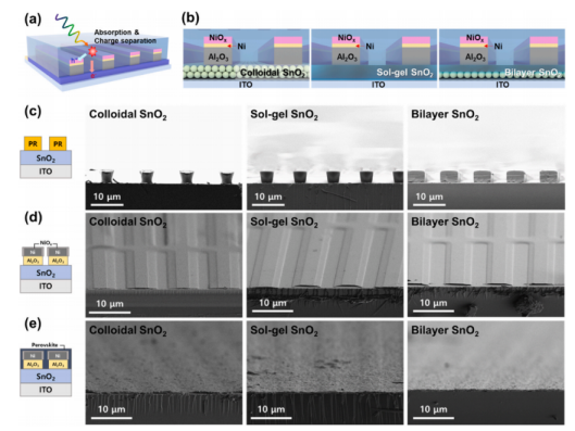
(a) Schematic diagram of the back-contact perovskite solar cell quasi-interdigitated electrode; (b) BC-PSC cell structure using different ETLs; after photolithography process (c) Al₂O₃/Ni evaporation and Ni oxidation (d) perovskite deposition (e) cross-sectional SEM image.
Back-contact interdigitated design: NiO₂ serves as the hole transport layer (HTL), and SnO₂ as the electron transport layer (ETL). Comparison of three ETL preparation schemes:
Colloidal SnO₂: Poor photolithography adhesion, low electrode patterning yield;
Sol-gel SnO₂: Improved pattern fidelity;
Double-layer SnO₂: Combining nanoparticles with a sol-gel layer to achieve high uniformity.
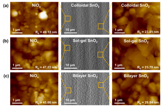
AFM and SEM images of perovskite thin film morphology: (a) colloidal SnO₂, (b) sol-gel SnO₂, (c) bilayer SnO₂
Morphology control: The contact angle of bilayer SnO₂ (53.54°) is moderate, promoting the growth of large perovskite (FAPbI₃)₀.₉₇ (MAPbBr₃)₀.₀₃ crystals, while colloidal SnO₂ (12.72°) results in small crystals due to excessive nucleation.
Interface characteristics
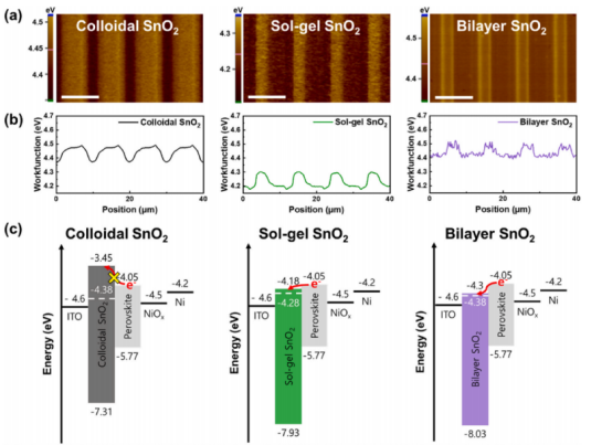
(a) KPFM measurement of contact potential difference (CPD) image (b) Linear CPD distribution on different SnO₂ surfaces; (c) Band alignment schematic based on ETL
Energy level alignment: KPFM shows that the CPD (0.12 eV) of double-layer SnO₂ is the highest, and the work function (4.39 eV) matches the perovskite conduction band optimally, enabling efficient extraction of electrons.
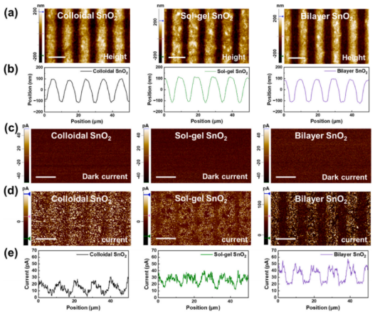
(a) C-AFM topography image; (b) topography linear distribution; (c) dark current plot; (d) photocurrent plot under illumination; (e) photocurrent signal distribution between electrodes
Photocurrent mapping: C-AFM confirmed that the average photocurrent of the double-layer SnO₂ (33.67 pA) was significantly higher than that of the sol-gel (26.69 pA) and colloidal (14.65 pA) samples, indicating an extended carrier diffusion length.
Photovoltaic performance and stability
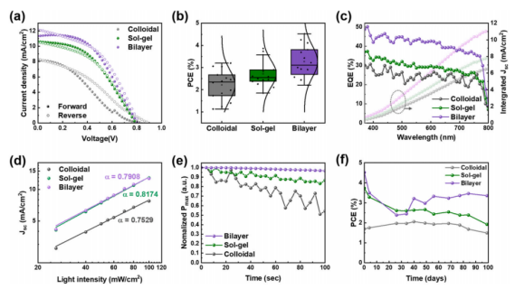
(a) J-V curve; (b) PCE box plot; (c) EQE spectrum and integrated Jsc; (d) Light intensity dependence of Jsc; (e) MPPT test; (f) Stability test
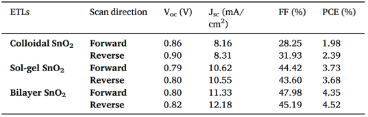
Optimal photovoltaic parameters of BC-PSCs (scanning direction: forward/reverse)
J-V characteristics: In reverse scanning, the maximum power conversion efficiency (PCE) of the double-layer SnO₂ cell reaches 4.52%, with a short-circuit current density (Jsc) of 12.18 mA/cm² and an open-circuit voltage (Voc) of 0.82 V; the gel SnO₂ cell has a PCE of only 2.39%, while the sol-gel - gel SnO₂ cell PCE is approximately 3.68%.
External quantum efficiency (EQE): The double-layer SnO₂ cell has the highest EQE, with an integrated Jsc value of 11.36, indicating more efficient light response and charge transport.
Stability: In maximum power point tracking (MPPT) tests, the double-layer SnO₂ cell demonstrates superior stability compared to the other two types. In an argon atmosphere, all cells showed no significant efficiency degradation over more than 100 days, with the double-layer SnO₂ maintaining the highest efficiency throughout.
Back-contact perovskite solar cells (BC-PSCs) avoid front electrode light shading issues due to their rear-side electrodes, but low interface charge extraction efficiency and severe recombination losses severely limit their performance. A double-layer SnO₂ electron transport layer (ETL) (nanoparticle SnO₂ + sol-gel SnO₂) was proposed, which optimizes interface energy level alignment and reduces defect states to enhance charge collection efficiency. The MPPT maintenance rate exceeded 95% (1,000 hours), validating that the interface engineering of the double-layer SnO₂ significantly improved operational stability.
Millennial Perovskite Maximum Power Point Tracking Test (MPPT)
email:market@millennialsolar.com
The Perovskite Maximum Power Point Tracking Test (MPPT) utilizes an A+AA+ grade LED solar simulator as the aging light source, leveraging its advanced technology and multi-functional design to provide robust support for research into perovskite solar cells.
▶ Light source grade: A+AA+, spectral matching grade A+, uniformity grade A, long-term stability grade A+
▶ Effective spot size: ≥250×250 mm (customizable)
▶ Adjustable light intensity: 0.2–1.5 sun, adjustable in 0.1 sun increments
▶ Independent power control: 300–400 nm/400–750 nm/750–1200 nm
Millennial perovskite maximum power point tracking (MPPT) test is not only a performance verification tool but also a decision-making basis for revealing material dynamic degradation mechanisms and driving interface engineering optimization. The outstanding performance of the double-layer SnO₂ in MPPT testing is a key proof of its core value as the transmission layer in high-efficiency and stable BC-PSCs.
Related Products


