
Quantum Efficiency Tester
PL/EL Integrated System
PV-Reflectumeter
3D Confocal Microscope
In-Line Four Point Probe Tester
Four Point Probe Tester
In-Line Thin Film Thickness Tester
Raman Spectrometer
FTIR Spectrometer
Spectrophotometer
Automatic Spectroscopic Ellipsometer
Contact Resistance Tester
Ultra depth of field 3D microscope
Auto Visual Tester
VMM PV Vision Measuring Machine
Solar Cell Horizontal Tensile Tester
Steady State Solar Simulator for Solar Cell
Solar Cell UV Aging Test Chamber
Solar Cell Comprehensive Tensile Tester
Visual Inspection Tester
Wet Leakage Current Tester
PV Module EL Tester
PV Module UV Preconditioning Chamber
Steady State Solar Simulator for PV Module
Current Continuous Monitor
Potential Induced Degradation Test
Bypass Diode Tester
LeTID Test System
Reverse Current Overload Tester
Impulse Voltage Tester
Hipot Insulation Tester
Ground Continuity Tester
Hipot Insulation Ground Tester
Damp Heat Test Chamber
Humidity Freeze Test
Thermal Cycle Test Chamber
Dynamic Mechanical Load Tester
Static Mechanical Load Tester
Hail Impact Tester
Robustness of Termination Tester
Module Breakage Tester
Cut Susceptibility Tester
Peel Shear Strength Tester
Universal Testing Machine (Single-arm)
Universal Testing Machine (Double-arm)
Glass Transmittance Tester
Acetic Acid Test Chamber
EVA Degree of Crosslinking Test System
Junction Box Comprehensive Tester
Drop ball tester
Semi-automatic scanning four-probe tester
Stylus Profilometer
Maximum Power Point Tracker
Perovskite Glass Transmittance Tester
Perovskite P1 Laser Scribing Multifunctional Testing Machine
Perovskite Online PL Tester
Perovskite Online Sheet Resistance Tester
Online Perovskite Film Thickness Tester
Perovskite Process Inspection Workstation
Portable EL Tester
Portable Thermal Imaging Tester
Solar Module Multi-Channel Testing System
PV Inverter Power Quality Tester
Drone EL Tester
IV Tester
IVEL Cell Sorting Machine
Solar Panel Production Process—Lamination
Date : 4 December 2025Views : 1400
The lamination process for Solar Panels is the core step determining their performance and lifespan! Using high-temperature and high-pressure technology, it “fuses” materials such as solar cells, glass, and EVA adhesive film into a robust integrated unit. This not only enhances power generation efficiency but also ensures the module's stability under extreme environmental conditions.
Laminator Working Principle:
The main structure of a laminator consists of the following components
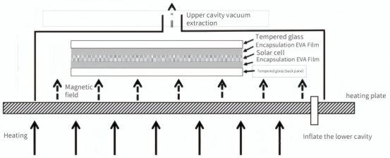
Base Plate: Also known as the heating plate, its surface is flat without protrusions or depressions. Typically, it contains high-temperature oil or electric heating rods to heat the base plate to the desired temperature.
Upper Cover: Equipped with a silicone plate, sealing rings, and other components. It can be pressurized via an inflation pipe to inflate the silicone plate, applying pressure to the assembly.
Upper Chamber: The space between the silicone sheet and the upper cover.
Lower Chamber: The space between the base plate and the upper cover.
Vacuum Pump: Used to evacuate air from either the lower or upper chamber.
Air Pump: Used to inflate either the lower or upper chamber.
With this understanding, we can now examine how the laminator operates. When the module enters the laminator, the following sequence begins:
Step 1: Lid Closure
The upper lid descends under hydraulic cylinder pressure until it reaches the qualified position. At this point, the sealing ring on the upper lid makes tight contact with the base, forming a sealed chamber known as the lower chamber.
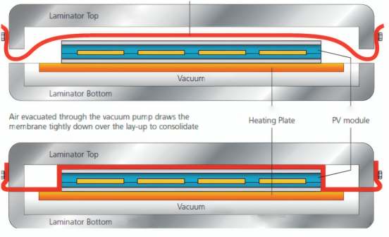
Step 2: Vacuum Extraction: The vacuum pump starts and begins the vacuuming process, which typically lasts about 6 minutes. During vacuuming, since the base plate is heated, the module is continuously heated after entering the laminator until it reaches the same temperature as the base. During this heating process, the adhesive film melts, transitioning from a solid to a liquid state. The vacuum environment allows gases trapped within the liquid adhesive film to escape from the module. This ensures the laminated module remains bubble-free.
Step 3: Gas-Pressure Laminating: The upper chamber is pressurized with air. The flexible silicone sheet deforms and expands, tightly conforming to the module under air pressure. This applies significant pressure to the module, forcing any remaining internal air bubbles to escape further. Simultaneously, the high temperature and pressure cause the flowing adhesive film to transition from liquid to solid state, initiating the cross-linking process. After inflation, the silicone sheet adheres tightly to the module, preventing the flowing adhesive film inside the module from completely escaping under pressure.
Schematic Diagram of Upper Inflatable Laminate
Step 4: Pressure Maintenance: After the upper chamber is pressurized to a specific level, it maintains constant pressure for a set duration. During this period, the adhesive film gradually crosslinks until the desired degree of crosslinking is achieved. At this point, the lower chamber can be pressurized to release the vacuum state, while the upper chamber is evacuated to relieve pressure. The upper cover separates from the base plate, and the component can be transferred to the cooling chamber for cooling before being discharged.
Pressure Holding Diagram
Note:
① The module does not come into direct contact with the silicone sheet or base plate; instead, a layer of non-stick cloth is interposed (to prevent the melted adhesive film from adhering to the base plate and silicone sheet).
② Modern Solar Panel laminators typically operate in three distinct chambers across three sequential stages:
Stage 1: Apply a low temperature to the substrate to melt the adhesive film. Evacuate the chamber and apply a low pressure to facilitate film melting and remove internal bubbles from the module.
Stage 2: Increase the substrate temperature significantly. Maintain vacuum conditions while applying high pressure to induce film cross-linking.
Stage 3: Vacuum is applied with very low pressure, while the substrate maintains a temperature around 20°C to cool the module.
This three-stage process is implemented to enhance the laminator's operational efficiency.
The primary purpose of the first stage is to melt the encapsulant and expel air bubbles. Therefore, the temperature should not be excessively high, and the pressure should not be too great. Otherwise, the encapsulant will cross-link prematurely, preventing internal bubbles from being properly expelled, resulting in bubbles within the module. (Typically around 120°C)
The second stage primarily aims to cross-link the encapsulant film. Therefore, higher temperatures and greater pressure are applied to accelerate the cross-linking process (around 140°C).
The third stage, cooling, is solely for cooling the module. Only minimal pressure is applied to prevent deformation or warping during the cooling process.
Some Abnormalities in Module Laminating Process
① Bubbles on cell surface: May result from excessive temperature during a specific stage, where bubbles were not fully evacuated before the film began cross-linking, trapping bubbles inside the module; abnormal vacuum extraction, insufficient vacuum rate preventing proper bubble removal; or insufficient vacuum extraction time.
② Snowflake-like bubbles at edges or corners: Caused by improper laminating frame height or size.
③ Insufficient tensile strength or crosslinking degree: Caused by low temperature, insufficient pressure, inadequate pressure holding time, or substandard laminating film quality.
④ Cell fragmentation after lamination: Resulting from excessive lamination pressure, foreign objects on the high-temperature cloth, or surface irregularities.
⑤ Bubbles around solder ribbons: Attributed to poor flux quality or insufficient flux drying.


